In today's episode of Radiator Game I would like to present you a thermal analysis of a room for walls insulated in a modern way, i.e. with polystyrene and cellular concrete. Of course, we will perform the simulation using the virtual layers method on the boundary condition of the model walls.
 |
| Modern Walls Analysis in Ansys Fluent |
First, we need to define the material properties of cellular concrete and polystyrene. Cellular concrete (red frame) with a thickness of 0.24 [m] will have the following parameters: thermal conductivity 0.15 [W / mK], heat capacity 800 [J / kgK] and density 1200 [kg / m3]. Polystyrene (blue frame) with a thickness of 0.15 [m] will have the following parameters: thermal conductivity 0.042 [W / mK], thermal capacity of 1300 [J / kgK] and density 25 [kg / m3]. We leave all the settings of the solvers and the models used unchanged as in the previous episodes of Radiator Game.
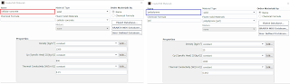 |
| Thermal properties of cellular concrete and polystyrene in Ansys Fluent |
A key step in modeling is the proper definition of the Modern Wall layers. As mentioned before, our wall consists of two types of materials with different thicknesses. To define this type of thermal resistance, turn on the Shell Conduction option (1). After that, press the Edit key (2). A definition window will appear in which we will define the number of layers, what materials will be made of and what thickness they will be. In our case, we set two layers of the wall (Number of Conduction Layers). In the first layer (green frame) we define cellular concrete with a thickness of 0.24 [m]. We leave the Heat Generation Rate unchanged because our virtual layer will not be a source of heat. Then for the second layer (black frame) we define polystyrene with a thickness of 0.15 [m]. As in the case of the first layer, the last field is left blank.
 |
| Virtual Multi-Layer Option in Ansys Fluent |
We make Virtual Multi Layers definitions for the boundary conditions of walls and roof. We will leave the rest of the BC's unchanged so that we can directly compare the obtained results with the previous analyzes that were included in previous entries.
Compared to the red brick wall, we obtained much higher temperatures in the room. In such an insulated room, we can feel comfortable because the temperature is above 20 C. However, a room made using the technique from 100 years ago could cause us to get flu or even corona :).
 |
| 3D Temperature Distribution in Room - Ansys Fluent |
Thanks to the good insulation properties of the walls, we have obtained a fairly uniform temperature distribution in the cross-section of the room.
 |
| Cross section Temperature Distribution in Room - Ansys Fluent |
The lowest temperatures, as predicted, occur in the window zone.
 |
| Temperature Distribution on Window Zone |
Below you can see the directions of air movement caused by the radiator. Comparing the thermal losses on the walls: for the red brick it was 33 [W / m2], while for the combined wall (cellular concrete / polystyrene) the losses were 7 [W / m2].
 |
| Gas Flow Movement - Vectors - Ansys Fluent |
If U want see previous episodes go links below :


0 Comments