Today I would like to present what differences in the obtained results can be expected in the two leading CFD programs from Ansys. It should be noted that most of the analysis settings (both for CFX and Fluent) remained in the default positions. Especially to test the differences, I chose the type of CHT analysis (conjugate heat transfer), thanks to which it is possible to analyze a wide range of output data.
 |
| Fluent vs CFX |
For CHT analysis, the same two-domain geometry was defined for both programs to perform the heat transfer analysis (default domain (gas -ideal gas air), kloc (steel solid domain).
The thermal parameters of air and steel were left in the default positions, only defining that the gas would have compressibility properties. The initial temperature of the system was 25 ° C but the log was preheated to 240 ° C. For a gas velocity of 50 m / s was defined for the inlet. Oultet was defined with a reference pressure of 1 atm ABS. The walls of the entire model (except inlet, outlet) were defined as adiabatic.
The total simulation time for both CFD programs was defined for 48 seconds. The analysis step size was defined as 1 second.
A model of heat transfer and transport was adopted for the turbulent gas model. More specifically, all boundary conditions and solver settings for Fluent and CFX will be explained in more detail in the next posts.
 |
| Boundary conditions for both CFX and Fluent |
The number of finite elements, the number of nodes and the mesh quality are on a similar level for both cases.
 |
| Mesh quality for both CFD programs |
The residual equation graphs are within the accepted accuracy range, there are no major calculation errors generated.
 |
| Residual for both cases |
For both cases, the average temperature of the kloc volume is at a similar level and amounted to approx. 210 C at the end of the cooling process (ie after 48 seconds). Also, the nature of the curve is similar and shows a linear tendency for the analyzed time period.
 |
| Average temperature of the kloc volume for both cases |
For both cases, a measuring point was generated from which the temperature was read as a function of time. The point for both Fluent and CFX was located at the same location on the cross section of the model.
 |
| Monitor Point for validation of temperature for Fluent and CFX |
The temperature curves read from the measurement point (monitor point) are presented below. As you can see, the lower values were obtained for the CFX program. Values are lower by more than 5%.
 |
| Temperature curves generated based on Monitor Point for both cases |
However, greater differences can be observed for the minimum temperature value from the volume of the kloc. Of course, it is automatically searched for across the entire solid and can be found in different places for Fluent and CFX for comparison steps. As can be seen from the results obtained, for the time of 48 s the difference is almost 10% (lower Fluent values).
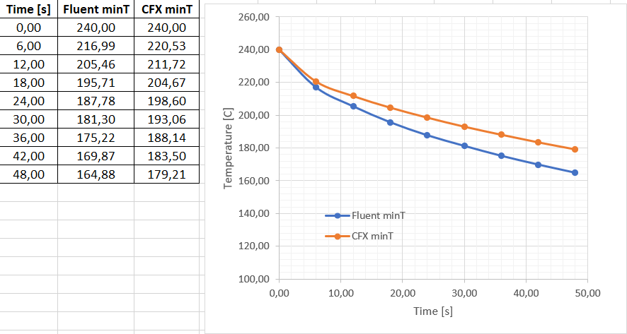 |
| Temperature curves generated based on minimal value from volume of kloc for both cases |
Quite significant differences can be seen in the formed stream of gas exiting the nozzle for both cases. With the CFX program, the gas stream sticks more to the block.
 |
| Velocity distribution on cross-section for both cases |
As it results from the obtained temperature distribution per kloc, the cooling intensity is higher for the Fluent program. It is caused mainly by the phenomenon of "sticking" of the stream to the kloc in CFX.
Differences in distribution and cooling intensity are also caused by different default thermal properties of steel for both programs.
Steel density - 8030 kg / m3 (Fluent), 7854 kg / m3 (CFX)
Conductivity - 16.3 W / mK (Fluent), 60.5 W / mK (CFX)
Thermal capacity - 502.5 J / kgK (Fluent), 434 J / kgK (CFX)
 |
| Temperature distribution for both cases (cross section of kloc) |
This post was intended to show how an inexperienced user of CFD programs may be exposed to generating quite serious calculation errors if he does not pay attention to the general aspects of modeling. The selection of models, material properties, the selection of solvers and the generation of a high-quality mesh are basic factors in the correct modeling of CFD phenomena.
Therefore, you need to pay special attention to the assumptions for CFD simulation.
An interesting fact is the calculation time for both cases (both analyzes were calculated on the same computer). The total calculation time for Fluent was 5m 30s and for CFX it was 10m 22s.


0 Comments