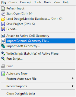
It often happens that our geometry generated in Design Modeler requires modification. Our model may be incomplete or we need to replace some elements. In such circumstances, it is worth using the Import External Geometry function.
 |
| Example of Improted Shaft (green) to Design Modeler |
Geometry import in Design Modeler (DM) takes place in two stages. In the first stage, we import the geometry (it can be to the default position). In the second step, we change the imported element to the target orientation. The geometry import function is shown in the figure below.
 |
| Import function in Design Modeler - Ansys Workbench |
When our imported geometry is in the default position in the DM workspace, we can proceed to the next step.In this stage, we will use the Body Transformation function thanks to which we will move our element to the indicated position. This function is also useful in transferring our entire model to the origin of the coordinate system, which is extremely important primarily in analyzes where we use periodicity and symmetry as a simplification of geometry.
 |
| Body Transformation Function in Design Modleler |
There are five functions available in Body Transformation. The Move option allows us to move our model relative to the coordinate system. As I mentioned earlier, this is a very helpful function in transferring our model to the origin of the main coordinate system or orienting an indicated model element which it will be related to the origin of the coordinate system. Another function is Translate which allows us to orient an element towards any point, line or plane. This function is mostly used to correctly orient the elements to each other. Thanks to the Rotate function, we are able to rotate our element in relation to the main axis of the coordinate system or the indicated line on the geometry. If we have a half of the model or we want to duplicate some elements, we use the Mirror function.
The last feature the most interesting is the Scale option. It is very helpful, first of all, in a quick gemoetric modification of the model if, for example, we want to check the influence of the nozzle diameter on the heat transfer from a given surface. Thanks to the use of this function, we do not need to drastically modify the next stages of modeling. At the end of this post, this feature will be described in more detail.
 |
| Example of default oriented shaft after import in Design Modeler |
In our post, we will use the Translate function to correctly orient the Shaft. After selecting the Translate option and selecting our geometry, we must define the translation axis (on the geometry line or the axis of the main coordinate system). After that, we only need to enter the value of the displacement. In the example shown, I used the Translate function twice because I orientated the shaft in two axes.
Of course, if we do not know the exact position of the imported geometry, the position of a given element should be measured using the ruler available in Design Modeler.
 |
| Correct oriented Shaft on the axis of rotation |
As mentioned before, now we will go into more detail about the Scale function and its capabilities. For the purpose of this task, the plate model with a hole was uniformly scaled to 10% of its size.
In the Scale option, we have two modes: Uniform and Non-Uniform. In the Uniform mode we scale the dimensions of the model in each axis, while in Non-Uniform we can scale the dimensions along the axis of interest. We have 1 as the default value, so if we want our model to be 200% larger, we enter the value 2, if we want to reduce it, for example, to a scale of 1:10, we enter the value 0.1. The non-uniform option is especially useful if you want to shorten the length of a rectilinear element.
Scale Option in Design Modeler
 |
| Options in Scale Function Ansys Design Modeler |


No comments:
Post a Comment