Friday, September 8, 2023

πŸ’₯πŸ’₯πŸ’₯ What is species model in Ansys Fluent and what is use for ? 🧐

Species model in Ansys Fluent is a feature that allows you to model the mixing and transport of chemical species by solving conservation equations describing convection, diffusion, and reaction sources for each component species¹. You can use this model to simulate non-reacting or reacting flows, with reactions occurring in the bulk phase, on wall or particle surfaces, or in the porous region². You can also choose different reaction mechanisms and rate formulations to suit your problem³.

Some examples of applications that use species model in Ansys Fluent are:

- Combustion modeling using finite-rate chemistry²

- Chemical vapor deposition (CVD) processes²

- Fuel cell modeling

- Electrochemical reactions

Source:

(1) ANSYS FLUENT 12.0 User's Guide - 33.3.17 Species Model Dialog Box - ENEA. https://www.afs.enea.it/project/neptunius/docs/fluent/html/ug/node1036.htm.

(2) ANSYS FLUENT 12.0 User's Guide - 15. Modeling Species Transport and .... https://www.afs.enea.it/project/neptunius/docs/fluent/html/ug/node512.htm.

(3) ANSYS FLUENT 12.0 Theory Guide - 7. Species Transport and Finite ... - ENEA. https://www.afs.enea.it/project/neptunius/docs/fluent/html/th/node126.htm.

How to define species model in Ansys ? 

To model species transport and finite-rate chemistry in Ansys Fluent, you need to follow these steps:

- Enable the **Species Transport** model in the **Species Model** dialog box. You can also choose the **Non-Premixed Combustion** model if you want to simulate turbulent reacting flow using the non-premixed combustion model¹.

- Define the **species** that are involved in your problem. You can add or remove species from the list of available species in the **Boundary Species** section of the **Species Model** dialog box¹.

- Define the **reactions** that occur in your problem. You can choose from different reaction mechanisms and rate formulations in the **Reactions** section of the **Species Model** dialog box¹. You can also specify the **reaction zones**, where the reactions take place, and the **reaction orders**, which determine how the reaction rates depend on the species concentrations².

- Define the **boundary conditions** for your problem. You can specify the **species mass fractions**, **temperature**, and **reaction rates** at the inlet, outlet, wall, or other boundaries².

- Initialize and run the calculation. You can monitor the **species mass fractions**, **temperature**, and **reaction rates** during the solution process².


Source: 

(1) ANSYS FLUENT 12.0 User's Guide - 33.3.17 Species Model Dialog Box - ENEA. https://www.afs.enea.it/project/neptunius/docs/fluent/html/ug/node1036.htm.

(2) 15. Modeling Species Transport and Finite-Rate Chemistry - ENEA. https://www.afs.enea.it/project/neptunius/docs/fluent/html/ug/node512.htm.

(3) 15. Modeling Species Transport and Finite-Rate Chemistry - ENEA. https://www.afs.enea.it/project/neptunius/docs/fluent/html/ug/node512.htm.

(4) #Ansys Fluent Tutorial | Modeling Species Transport and Gaseous .... https://www.youtube.com/watch?v=HcX1t9EDpSs.

What are differences between species model and Euler model in Ansys Fluent

The species model and the Euler model are two different approaches for modeling multiphase flows in Ansys Fluent. The species model is used to model the mixing and transport of chemical species by solving conservation equations describing convection, diffusion, and reaction sources for each component species³. The Euler model is used to model the interpenetrating continua of different phases by solving a set of momentum and continuity equations for each phase².

Some of the differences between the species model and the Euler model are:

- The species model is suitable for non-reacting or reacting flows, with reactions occurring in the bulk phase, on wall or particle surfaces, or in the porous region³. The Euler model is suitable for granular (fluid-solid) flows or nongranular (fluid-fluid) flows, with coupling achieved through the pressure and interphase exchange coefficients².

- The species model shares a single set of momentum equations by the fluids, and tracks the volume fraction of each of the fluids in each computational cell³. The Euler model solves a separate set of momentum equations for each phase, and accounts for the phasic volume fractions that sum up to one².

- The species model requires the definition of species, reactions, reaction zones, and reaction orders³. The Euler model requires the definition of interphase drag, lift, wall lubrication, turbulent dispersion, and virtual mass forces².


Source: 

(1) ANSYS FLUENT 12.0 User's Guide - 15. Modeling Species Transport ... - ENEA. https://www.afs.enea.it/project/neptunius/docs/fluent/html/ug/node512.htm.

(2) ANSYS FLUENT 12.0 Theory Guide - 16.2.1 Approaches to Multiphase Modeling. https://www.afs.enea.it/project/neptunius/docs/fluent/html/th/node293.htm.

(3) ANSYS FLUENT 12.0 User's Guide - 33.3.17 Species Model Dialog Box - ENEA. https://www.afs.enea.it/project/neptunius/docs/fluent/html/ug/node1036.htm.


Wednesday, September 6, 2023

😊😊😊 How to change workspace in Ansys Workbench (Design Modeler)? 😊😊😊

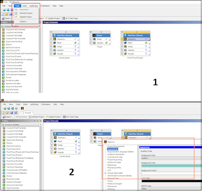
 If U want to change, for example background in Ansys Design Modeler, U only need follow two simple steps. Below You can find short instruction how to do it. 

Two simple steps to change background in Ansys Design Modeler

1. First U need to open Ansys Workbench Workspace 

2. Click on Tools (red frame)  - and pick Options (1) 

3. Next click on Apperance  - Then U can change Graphic Style 

I think , that after changes, your workflow will be more efficient. 

Below U can find other instructions how to change workspace in Ansys Workbench

To change the workspace in DesignModeler ANSYS, you can follow these steps:

  • Open Workbench and create a new project or open an existing one.
  • Right-click on the Geometry cell and select DesignModeler as the geometry editor. If DesignModeler is not listed, you may need to install it separately from the ANSYS Student website.
  • Double-click on the Geometry cell to launch DesignModeler. You will see a default workspace with a 3D view and a tree outline on the left.
  • To customize the workspace, you can use the View menu to change the display options, such as grid, axes, units, etc. You can also use the Tools menu to access various tools, such as sketching, modeling, parameters, etc.
  • To save the workspace settings, you can use the File menu and select Save Settings As. You can also load a previously saved workspace by selecting Load Settings.
  • To exit DesignModeler and return to Workbench, you can use the File menu and select Exit.

I hope this helps you with your question. If you need more information, you can check out these web search results . 😊

To change the background color in ANSYS DesignModeler, you can follow these steps:

I hope this helps you with your question. If you need more information, you can check out these video tutorials.  πŸ˜Š

Tuesday, September 5, 2023

πŸ’₯πŸ’₯πŸ’₯ #12steps Ansys Fluent Tutorial Rotating Fan in Steady State 🧐🧐🧐

 Below You can find two parts of tutorial  - how to model rotating fan in Ansys Fluent. The first episode is in Steady State  - frame motion model. 


Friday, September 1, 2023

What is Digital Twin in Ansys and capabilities of dedicated software for this Twin Builder

 A digital twin is a connected, virtual replica of an in-service physical asset that uses simulation and data to mirror the real-world experience of that product¹. A digital twin can be used for system design and optimization, predictive maintenance, and industrial asset management².

Ansys is a software company that provides simulation-based solutions for various engineering domains. Ansys Twin Builder is one of the products that Ansys offers for creating and deploying digital twin models². Ansys Twin Builder allows engineers to build, validate, and deploy simulation-based digital twins with hybrid analytics². Hybrid analytics combines machine learning and physics-based approaches to achieve more accurate predictions².

Some of the capabilities of Ansys Twin Builder are:

- It can integrate real-world data from sensors and IoT platforms with simulation models to create a digital twin that reflects the current state and behavior of the physical asset².

- It can run simulations faster and more efficiently using reduced-order models (ROMs) that capture the essential dynamics of the system without compromising accuracy².

- It can support various types of systems, such as fluid, structural, electromagnetic, thermal, and power systems, using Ansys' multidomain simulation expertise².

- It can validate the performance and reliability of the digital twin using Ansys' solver technology and model libraries².

- It can deploy the digital twin to any platform, such as cloud, edge, or on-premise, using Ansys' runtime capabilities and APIs².


You can find more information about Ansys Twin Builder on the [Ansys website](^2^) or read some case studies and examples on the [Fluid Codes website](^3^) or the [Finite Element Analysis website](^4^).

Source:

(1) Digital Twin Simulation-Based Software | Ansys. https://www.ansys.com/products/digital-twin.

(2) Ansys Twin Builder | Create and Deploy Digital Twin Models. https://www.ansys.com/products/digital-twin/ansys-twin-builder.

(3) Ansys Twin Builder | Create and Deploy Digital Twin Models. https://www.ansys.com/products/digital-twin/ansys-twin-builder.

(4) A working example of a Simulation-enabled Digital Twin. https://www.finiteelementanalysis.com.au/featured/simulation-enabled-digital-twin/.

(5) SIMULATION PRODUCT HANDPRINT: DIGITAL TWINS - Ansys. https://www.ansys.com/content/dam/amp/2022/july/asset-creation/esg-ebooks/ansys-esg-digital-twin.pdf.

What are the generaΕ‚ steps to build Digital Twin in Ansys Twin Builder ? 

The general steps to build a digital twin on Twin Builder Ansys are:

- Build your twin: You need to create a system-level simulation model of your physical asset using Ansys' multidomain simulation expertise and solver technology. You can also integrate third-party tools and 3D models within your system simulation using reduced-order models (ROMs), which are simplifications of 3D models that preserve the essential information and run faster²⁴.

- Validate your twin: You need to verify and validate the performance and reliability of your digital twin model using Ansys' model libraries and test scenarios. You can also compare the simulation results with real-world data from sensors and IoT platforms to calibrate and improve your model².

- Deploy your twin: You need to deploy your digital twin model to any platform, such as cloud, edge, or on-premise, using Ansys' runtime capabilities and APIs. You can also connect your digital twin with real-time data streams from your physical asset and monitor its operation and health remotely².

You can find more information about how to build a digital twin on Twin Builder Ansys on the [Ansys website](^2^) or watch some video tutorials on [YouTube](^1^) ²³.

Source: 

(2) Build, Validate and Deploy Simulation-Based Digital Twins with Ansys. https://www.youtube.com/watch?v=qAsTDoosc2o.

(3) How to Build a Digital Twin from a Systems Simulation | Ansys. https://www.ansys.com/blog/how-to-build-a-digital-twin-from-a-systems-simulation.

(4) Build, Validate and Deploy Simulation-Based Digital Twins with Ansys. https://www.youtube.com/watch?v=qAsTDoosc2o.

πŸ’₯ #12steps tutorial Ansys Design Modeler How to create plane, patterns and substract volumes 🧐

 A plane in ANSYS Design Modeler is a flat surface that can be used to create sketches or other geometry features. There are different ways to create a plane in ANSYS Design Modeler, depending on the reference geometry and the orientation of the plane.

Some of the methods to create a plane are:

  • From Plane: This method creates a new plane by offsetting or rotating an existing plane. You can specify the distance and angle of the transformation, or use the drag handles to adjust the position and orientation of the new plane.
  • From Face: This method creates a new plane that is parallel to an existing face of a solid or surface body. You can specify the offset distance from the face, or use the drag handle to move the new plane.
  • From Centroid: This method creates a new plane that passes through the centroid of a selected body, edge, or vertex. You can specify the normal direction of the plane, or use the drag handles to rotate the plane.
  • From Circle/Ellipse: This method creates a new plane that is tangent to a selected circle or ellipse. You can specify the offset distance from the circle or ellipse, or use the drag handle to move the new plane.
  • From Point and Edge: This method creates a new plane that passes through a selected point and is parallel to a selected edge. You can use the drag handles to rotate or move the new plane.
  • From Point and Normal: This method creates a new plane that passes through a selected point and has a specified normal direction. You can enter the normal vector components, or use the drag handles to rotate the plane.
  • From Three Points: This method creates a new plane that passes through three selected points. The points can be vertices, sketch points, or points on edges or faces.
  • From Coordinates: This method creates a new plane that has a specified origin and normal direction. You can enter the coordinates of the origin and the normal vector components, or use the drag handles to adjust the position and orientation of the new plane.

To create a plane using any of these methods, you need to follow these steps:

  1. Open ANSYS Design Modeler and create or import your geometry.
  2. In the Tree Outline, right-click on XYPlane, YZPlane, or ZXPlane and select Insert > Plane.
  3. In the Details View, select the method you want to use from the Type drop-down list.
  4. Select the reference geometry (plane, face, edge, vertex, point, circle, ellipse) as required by the method.
  5. Specify the parameters (distance, angle, normal vector) as required by the method, or use the drag handles to adjust the position and orientation of the new plane.
  6. Click Generate to create the new plane.

You can also watch some video tutorials on how to create planes in ANSYS Design Modeler:

I hope this helps you understand how to create planes in ANSYS Design Modeler. 😊

πŸ’₯πŸ’₯πŸ’₯ Strength analysis of rotating FAN Ansys Static Structural Tutorial 🧐

Strength analysis is a type of finite element analysis that is used to determine the stress and strain of a structure or a component under various loads and boundary conditions. ANSYS is a software that provides a comprehensive suite of tools for performing strength analysis and other types of engineering simulations.

If you want to learn more about strength analysis in ANSYS, you can check out some of these resources:

  • [A tutorial on how to perform strength analysis of a beam in ANSYS]
  • [A video on how to perform strength analysis of a plate in ANSYS]
  • [A course on strength analysis using ANSYS]

I hope this helps. 😊

: Finite Element Analysis - an overview | ScienceDirect Topics : ANSYS - Wikipedia : Strength Analysis of Beam in ANSYS - Tutorial for Beginners - YouTube : Strength Analysis of Plate in ANSYS - Tutorial for Beginners - YouTube : Strength Analysis using ANSYS | Udemy

πŸ’₯ #12steps tutorial Ansys Design Modeler How to draw a fan 🧐


Design modeler ansys is a software tool for *geometric modeling* that allows you to create and modify your models in preparation for your analysis in ansys workbench. Ansys workbench is a platform for *computational fluid dynamics (CFD)* and *finite element analysis (FEA)* that can simulate various phenomena involving fluid flow, heat transfer, and chemical reactions. Design modeler ansys is intended for both CFD and FEA users. ¹² #computerscience #engineer #engineering #scienceandtechnology #ansys #fea #cae #simulation #mechanicalengineering #creativity #projects #consultants #industrialengineering #productdesign #productdevelopment #industrialdesign #automotive With design modeler ansys, you can: - Import and export models from various CAD formats, such as SolidWorks, Catia, UG, etc. ¹³ - Create and edit parametric models using sketching, extrusion, revolution, sweep, loft, blend, etc. ¹⁴ - Apply Boolean operations, such as unite, subtract, intersect, etc., to combine or separate models. ¹⁴ - Modify models by adding or removing features, such as holes, fillets, chamfers, etc. ¹⁴ - Create and modify coordinate systems and planes to define the orientation and position of models. ¹⁴ - Define dimensions and constraints to control the size and shape of models. ¹⁴ - Create named selections and body interactions to assign boundary conditions and loads in ansys workbench. ¹⁴ Design modeler ansys has a graphical user interface (GUI) that consists of several panels, such as: - The *tree outline* panel that shows the hierarchy of the model components and allows you to select and edit them. ¹⁴ - The *graphics* panel that displays the model in 3D view and allows you to zoom, pan, rotate, etc. ¹⁴ - The *details view* panel that shows the properties and parameters of the selected component and allows you to change them. ¹⁴ - The *toolbar* panel that contains various icons for creating and modifying models. ¹⁴ - The *message* panel that shows the status and errors of the modeling process. ¹⁴ is better Ansys Design Modeler or Space Claim ??

- Import and export models from various CAD formats, such as SolidWorks, Catia, UG, etc. ¹³ - Create and edit parametric models using sketching, extrusion, revolution, sweep, loft, blend, etc. ¹⁴ - Apply Boolean operations, such as unite, subtract, intersect, etc., to combine or separate models. ¹⁴ - Modify models by adding or removing features, such as holes, fillets, chamfers, etc. ¹⁴ - Create and modify coordinate systems and planes to define the orientation and position of models. ¹⁴ - Define dimensions and constraints to control the size and shape of models. ¹⁴ - Create named selections and body interactions to assign boundary conditions and loads in ansys workbench. ¹⁴ Design modeler ansys has a graphical user interface (GUI) that consists of several panels, such as: - The *tree outline* panel that shows the hierarchy of the model components and allows you to select and edit them. ¹⁴ - The *graphics* panel that displays the model in 3D view and allows you to zoom, pan, rotate, etc. ¹⁴ - The *details view* panel that shows the properties and parameters of the selected component and allows you to change them. ¹⁴ - The *toolbar* panel that contains various icons for creating and modifying models. ¹⁴ - The *message* panel that shows the status and errors of the modeling process. ¹⁴

Popular posts