In today's post, I would like to show you a tutorial in Transient Thermal on the analysis of the influence of conductivity due to the different location of the same boundary conditions for the same geometry.
 |
| Influence of conductivity in Ansys Transient Thermal |
The first step is to generate a Transient Thermal program block. Then we load the geometry (red frame) or create it in the CAD module (SpaceClaim or Design Modeler).
 |
| How to load geometry in Ansys Workbench |
In the next step, we need to define the materials that we will use in our transient simulation. In our case, we will be dealing with two materials: Structural Steel and Concrete. In Engineering Data Sources (red box) we can use a rich material base. The basic materials are listed in the General Materials section (blue box). If we want to use the richer section, we can enter Thermal Materials and Fluid Materials (orange box). However, after entering one of the sections, we can select the material (after the arrow) by clicking the plus sign. After doing this, the selected material will appear in the Outline of Schematic window.
 |
| Defining materials in Engineering Data Section - Ansys Workbench |
After clicking on a given material (red frame), we can modify its thermal properties (blue frame). We can make each property (conductivity, heat capacity, density) dependent on temperature. Nonlinear dependencies will be displayed on the graph (orange frame).
 |
| How to modify thermal properties in Ansys Workbench |
After the exact definition of materials and their properties, click on the MODEL section to carry out the rest of the modeling stages.
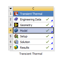 |
| Model Section in Ansys Workbench |
In the first analysis, we will define the heat flow in the direction of the X axis (red arrow). For this purpose, we will define a convection of 500 W / m2K (B) as the intensive cooling zone and on the opposite side of the model (C) we will add a convection of 5 W / m2K as the free cooling zone. We define the upper and lower walls (A) as adiabatic zones.
 |
| Boundary Conditions in Ansys Workbench - Transient Thermal |
The next stage is the moment when we assign previously defined materials to specific parts of the geometry. And so for the internal part we assign Structural Steel, and for the external part we assign Concrete.
 |
| How to assign materials to parts in Your geometry - Ansys Workbench |
In the tree in the Materials option, we can view the properties of our materials. We can also modify them from this level or create mixtures of materials (you can find the tutorial in previous entries).
 |
| Materials properties in Ansys Transient Thermal - Ansys Workbench |
If U want learn more about Ansys CFD (Fluent, CFX or other) try below links
https://howtooansys.blogspot.com/2021/11/how-to-quick-modify-geometry-to-make.html
https://howtooansys.blogspot.com/2021/11/classic-tutorial-flow-over-cylinder-in.html
https://howtooansys.blogspot.com/2021/11/wax-melting-in-ansys-fluent-simple-step.html


0 Comments